Needed tools and materials
In order to complete this exercise you need to procure the items listed below.
1. Arduino Kit
2. Arduino Sensors
3. MG995 Servo Motor
4. Small Umbrella
5. Caliper
Assignment
The purpose of this module is to explore mechanical linkages. This will enable you to create deployable systems that can expand and contract resulting in different interactions. The final objective of this module will be connecting your linkage system to the Sheikhabot and animate it using the Arduino micro-controller. The module is based in reverse engineering one of the oldest linkage systems, the umbrella. Through this process, you will learn more about the mechanics of an umbrella and develop the skills to create a linkage system of your own. Your linkages will be developed digitally on Rhino and will be simulated on software called Algodoo. Mechanical linkages are at the core of many kinematic systems. Understanding them will enable you to develop interactive devices and artifacts. Completing the various exercises within this module will also give you the necessary skills to create your Symbiotic Creature in the Studio.
Instructions
Step 1 | Dissect the umbrella
Watch this tutorial and follow the instructions below:
In this step you will analyze how an umbrella works, dissect it and understand about mechanical linkages and joinery systems, and use the dissection to reverse engineer the umbrella system. (You can buy the umbrella for 14dhs from Daiso).
- Buy a small umbrella
- Remove the umbrella canopy
- Dismantle all except one of the umbrella arms and measure all the components using a Caliper and take note.
- Create an orthogonal drawing in Scale 1:1 of the arm using a mechanical pencil & a ruler per the indications below:
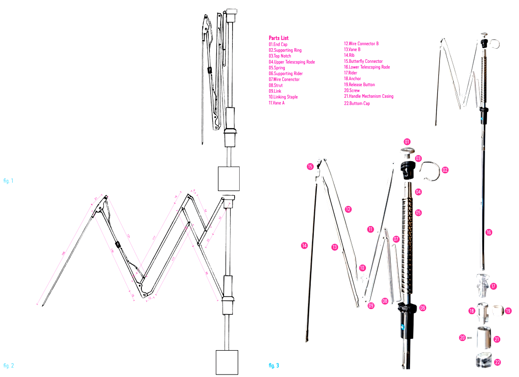
- In closed state as seen in fig. 1
- In semi-open state, add the dimensions to the drawing with Adobe Illustrator in magenta with the same line and font style as seen in fig. 2.
- Lay down on a white surface the elements that you dismantled earlier in point 4, and take a photo of the exploded view, remove the background with Adobe Photoshop, number and name the pieces in illustrator with the same style and text size as seen in fig. 3
- Refer to the Submission section below to know what to submit on the blog and eventually Moodle.
Step 2 | Animating the umbrella linkages digitally in Algodoo
Watch this tutorial and follow the instructions below:
In this step you will digitalise the dissected umbrella in Rhino, convert the rhino file into Algodoo using a DIDI exclusive Grasshopper script, and using Algodoo to digitally animate the linkage. Download and Install Algodoo (It’s Free).
- Import the drawing image done in point 4.2 of Step 1 in Rhino using the “Picture”command
- Scale the image so it’s 1:1 (make sure you’re working with mm units)
- Draw each linkage as a single curve on the imported image
- Hide the image, and fix the intersections, tolerance for errors is 0 as it will break the conversion script, hence sure the links are intersecting properly
- Download DIDIAlgodooConverter.gh and open it in grasshopper.
- Select (Step 2 – Umbrella Linkages) from the drop-down menu within the script.
- Assign the curves you just created leaning towards the left (\) to Top curves component within grasshopper, and the curves leaning (/) to the bottom curves. To assign, simply shift-select the curves in question, right-click on the component and set multiple curves.
- Right-click on the yellow panel in grasshopper and click on “stream contents” with destination as your desktop
- A file (Untitled.) will be created on your desktop and constantly updated as you do modification on rhino or grasshopper, add *.phn extension to it (so Untitled. becomes Untitled.phn)
- Open the file Untitled.phn with Algodoo
- If you don’t see your linkage system in Algodoo and you just get a blue screen, it can be for the following reasons (your linkage system is not valid, your intersections are not clean, you have the same color linkage overlap remember you have to work in pairs of opposite colors).
- If you face difficulty in having a valid linkage system, start from your umbrella and change that.
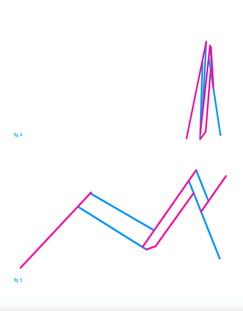
- Take a screenshot of the links in closed state as in (fig. 4) below
- Take a screenshot of the link in open state as in (fig. 5) below
- Video record the screen (without the menu) animating your linkage
- Make sure you save both the rhino and grasshopper files on your computer.
Step 3 | Creating your own linkages
Watch these 3 tutorials and follow the instructions below:
After dissecting the umbrella and familiarizing with Algodoo, the purpose of this phase is to alter the umbrella linkage and create your own. The new linkage will become the legs of your Sheikhabot the kits of which you should have already withdrawn from the campus by now. The goal is to create such linkages that can make the Sheikhabot move in unexpected ways (jump, drag, crawl, etc.). Although the exercise is to make 3 sets of identical legs and install them on the Sheikhabot, you can also make 3 different sets.
- Open the rhino curve file created in point 3 of the previous step.
- Vary the curves in such a way that the original linkage becomes unrecognizable leading way to new and interesting motions and hence eventually interesting behaviours of your robot.
- Assign the new curves to grasshopper as in point 7 of the previous phase
- Select (Step 3 – Sheikhabot) from the drop-down menu within the script.
- Repeat points 8 to 14 from the previous step for your new linkage assembly, repeat and iterate linkages until you are satisfied with the behaviour of the new system.
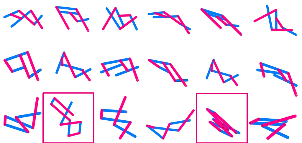
- Repeat 9 different times and document for the final submission (as fig. xy and zx), the idea is to get 9 different leg proposals and choose one of them for your Sheikhabot, each proposal needs to have at least 6 links. (as seen in fig. xy, note: this is just a reference you need 9 different proposals).
- Prepare a neutral assembly zone with a white background, and activate a TimeLapse capture for the next phase starting from the assembly to the final Animation, similar to the setting in the tutorial.
- Pick 1 of the 9 linkage system you designed and simulated with an interesting motion.
- Use the nuts and bolts to assemble the link
- Make 3 set’s of that linkage system and connect it to the Sheikhabot Assembly, you can also install 3 different linkage systems as long as it animates the bot in an unexpected way.
- Install the MG995 Servo Motor on your assembly
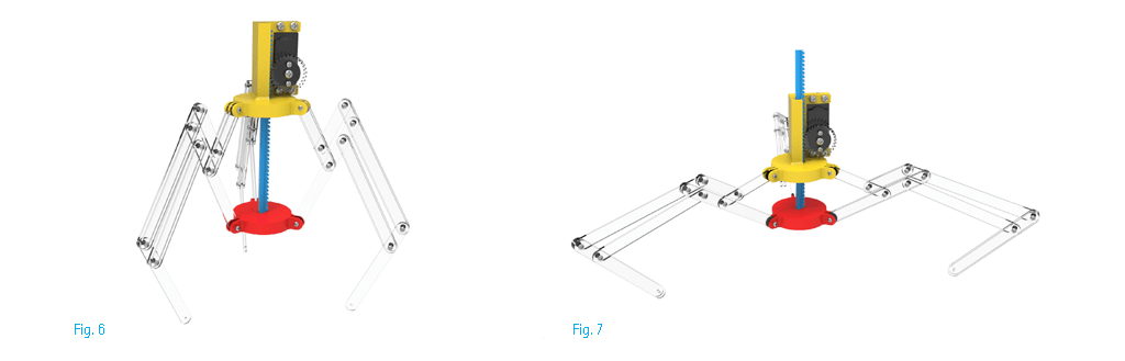
- Take a picture of the bot in closed state as in (fig. 6) and open state as in (fig. 7) without a background as seen in the examples below.
- Animate your Bot using Arduino on a well illuminated white neutral background area and save the Video. Download the Servo script from this link.
Submission
Following the examples above compile your submission in a similar way using
inDesign and Submit a single pdf file with the proper naming(Name_Surname_Linkages.pdf) on:
- Publish the pdf content (as an image file) and the videos on the Blog by 10th of April 2022 – 23:59.
- Publish the pdfs on Moodle together with the videos.
More details in the instructions below:
Step 1
• Insert in the Pdf the Orthogonal drawing of the umbrella arm in closed and open state as seen in fig. 1 and 2
• Insert in the Pdf the Exploded view of the umbrella with a Photoshoped white background named and as seen in fig. 3
Step 2
• Insert in the Pdf the screenshot of the links in closed state from Algodoo as in (fig. 4)
• Insert in the Pdf the screenshot of the links in open state from Algodoo as in (fig. 5)
• Rhino file of your drawing and curves (Name_Surname_Linkages.3dm)
• Video of your Algodoo animation (Name_Surname_Linkages.mov)
Step 3
• Insert in the Pdf the screenshot of the modified links in closed state from Algodoo
• Insert in the Pdf the screenshot of the modified links in open state from Algodoo
• Insert in the Pdf the two images with the 9 different leg proposal in open and closed state as in the example above, from Algodoo and highlight the one you picked as you can see in fig. xy above.
• Rhino file of your drawing and 9 curve proposals (Name_Surname_ModifiedLinkages.3dm)
• Videos of your Algodoo animations (Name_Surname_ModifiedLinkages.mov)
• Video of timelapse of Sheikhabot assembly and Animation
(Name_Surname_SheikhabotAssembly.mov)
• Insert in the Pdf a Picture of the bot with a neutral white background in closed state as in (fig. 6) and open state as in (fig. 7). Submit the high resolution photos of the bot separately in Moodle as well.
• Video of your Sheikhabot moving with the new linkages (Name_Surname_Sheikhabot.mov)
• A screenshot of your Arduino code
